|
Antenna Setup
This is the manual for installing a NVIS antenna. 
First let us consider some antenna basics. We are talking about a 'dipole' antenna. What is a dipole antenna? Well, the 'di' simply means that it is composed of two SEPARATE lengths of wire end to end with a 'drop line' between them that goes to your radio. In the picture above the drop line looks like two balls hanging down from the center. Drop lines must always be at the center point. The two long wires at the top (one on each side of the balls) COMBINED have a length of one-half the wave length - which is why this is called a half wave length dipole antenna. It being half wave length works out because there are 'harmonics' to the waves and we use that instead of the full wave length. The full wave length is just too long to deal with and has other complications besides. Since we are dealing with the 80m band, one half the wave length is 40 meters. Forty meters converts to (is the same as) 131 feet which means that by this method the two wires need to EACH be 65 and a half feet long. There are also vertical dipoles or peaked dipoles called inverted V's which are sort of shaped like a teepee. There are also various other configurations but what we are using/planning/describing is a plain old horizontal dipole which means that it is strung out horizontal to the ground. Now the big issue becomes one of how high above the ground should it be? The ideal height for distance transmission is said to be one eighth (1/8) of the wavelength. At 80 metres, one eighth of 80m is 10m and 10 meters is about 32 feet. But getting 131 feet of wire up 32 feet above the ground can be something of a stretch. Having the wire so high also creates a different problem. Radio waves also travel across the ground. Having the wire so high produces a wide ground wave. This means that the ground wave will reach further out to about 70 miles and be received by receiving radios slightly before the skywave. The two will interfere with each other and clutter the signal. This can be remedied by having the antenna low to the ground. How low? Some have recommended as low as 7ft. We have hit upon a compromise height of 12ft. As mentioned before, numerous other variables will enter in, such as the formation of the surrounding terrain and the soil conditions. Once again you will have what you will have - so probably not to worry about it. To compensate for the lower level some have advocated adding a ground reflecting wire such as you see at the bottom of the above picture. There is much debate as to the value (or disvalue) in doing this, but in our more elaborate design I add one. You can always take it off, if you find it doesn't make any difference, or it doesn't work for you. All this is just to warn you that no matter what kind of antenna and system we recommend that there will be some that will be adamantly proclaiming that we and you are doing it all wrong. You can study into the matter as much as you like but after a great amount of study we have arrived at the recommendation given here. Some Hams spend hundreds and even thousands of dollars on antennas but you may be willing to just string the antenna up between some trees, as I did originally and it worked/works quite well. But if you want to build ahead of time a better semi-portable but still relatively inexpensive antenna - there are plans below. The Drop Line No matter which design you choose you will need a 'drop line' which we show as being from the center of the antenna. Here too there can be a variety of designs but the simple principle shown below works just fine. This is a detail of what appears as the two balls hanging down in the previous picture. 
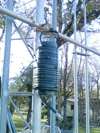
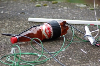
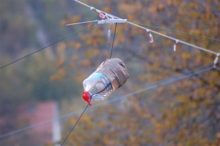
In the above diagram you can see that the two arms (the two long wires) of the dipole are not directly connected. There is in fact an insulator in between them - isolating them from each other. The wire in the bottom of the picture is plain old cable for hooking up a TV antenna. The outside braid goes to one wire and the center conductor to the other. The other end of this wire goes to the antenna connection on your radio which we discuss in the section about hooking up your radio. Using a Balun There is one other item that will often improve an antennas performance and that is a 'balun'. A balun's purpose is to allow connecting a balanced, (e.g., a dipole or driven element) to an unbalanced line such as coax which is not balanced, thus the name, Balun for balanced/unbalanced. The balun accomplishes this by presenting a high impedance (resistance), to RF currents flowing outside the coax shield. This forces the currents in each side of the driven elements to be equal. It is our intention to include a balun with the radio and antenna but once again - if you are building your own there are many simple designs on the Internet. The general concept is to take a piece of PVC pipe, put a couple of eyebolts in it to hang it up with, and wrap 18 to 21 feet of your coaxial dropline around it. From the previous diagram you can see how to hook the dropline from the balun onto the antenna. Below are three pictures of homemade baluns. One using PVC and the other two bottles. You can have fancy and neat connections, or even buy expensive baluns, but if you need to just make do, that is how to do this also. After all, we are talking about survival radio. The balun should be suspended just below the wire and neither lie on the ground or be attached to a grounded support as they are in two of the photos. The intent here being to show you how NOT to do it.
Building a Better Antenna First Step: Gathering the materials: (Should be completed on a day before starting construction) 1. First find three molds for concrete that are approximately 2ft in diameter - or they could be two feet square. They need to be approximately eight inches high. These could be some wornout small vehicle/trailer tires, rings sawed out of a small barrel, or just a box built out of scrap wood. 2. Next find a total of forty feet of 2" or greater rigid plastic pipe. It can be PVC or ABS and can be different for each of the three molds. It certainly doesn't need to be new. 3. Appropriate pipe glue 4. Six spikes (very large nails) for holding the pipes in the concrete. 5. 12 pieces of bent reinforcing rod or something similar for handles 6. Wire 7. A bag of concrete and sufficient sand and water
A tub or wheelbarrow in which to mix the concrete. A water hose or buckets to carry water in. A shovel to mix and move the concrete Pouring the concrete molds. (Should be done on a separate day from the rest of the construction.) When you are ready to pour the concrete into the molds, find a smooth surface to sit the molds on. This could be an old piece of plywood or just your driveway that you have covered with a piece of sturdy plastic so the concrete won't stick to your driveway. Cut a two and a half foot length of the plastic pipe to stand up in the middle of each of your molds. Four inches from the bottom of the pipe run through the pipe (at 90 degrees to each other) two approximately one foot long steel (iron whatever - they could be the big nails/spikes) rods that will stick out about 6 inches on each side of the pipe. These will hold the pipe in place in the concrete once the concrete is set. I like the idea of the open pipe being flush with the bottom of the mold so that water will drain out. It is absolutely essential that the pipe stand absolutely vertical in the mold. A little bit of a lean at the bottom will cause a lot of lean at the top. There is one more thing that I recommend before pouring concrete into the mold and that is that you prepare four handles for each mold. Something like upside down U shaped pieces of strong re-enforcing rod (mentioned in the material list) bent L shaped on the bottom so that they won't pull out of the concrete. Just before the concrete begins to set place these at four spots around the edge of the mold extending upwards out of the concrete so that after the concrete COMPLETELY sets, four individuals may each grab one and easily walk away with the set up concrete mold. Since the antennas are semi-portable, say in a pick-up truck or the trunk of a large car, this makes a great project where several users can gather together in one location for each to build their own antenna. Forming the masts on a third construction day Theoretically there needs to be only two masts - one at each end. Or one could make do with only one mast by tethering one end of the antenna to the corner of a building or a tree. But for a good horizontal antenna the strongest structure is three masts using one in the middle. To each of the plastic pipes that should be sticking out of the top of each of the molds for something less than two feet (and ideally about the same height) - attach (glue) a pipe coupler. The top part of the coupler will be left glue free for easy assembly and disassembly. Cut six five foot pieces of pipe (two for each mast). Glue a coupler onto just one end of three of the 2 foot pieces. This helps the smaller couplers from becoming lost and adds somewhat to the strength of the mast. You now have the option of placing your antenna two feet, seven feet, or twelve feet above the ground. Actually, you could cut additional sections of pipe and using additional couplers - push it up from the bottom and above the first coupling and insert additional sections of the mast. Even with guide wires it would become increasingly fragile. If you are insistent on having a higher antenna then it would be wise, using the same design, to start with larger diameter pipe, and to build a somewhat larger diameter base. Attaching the guy lines and antenna. You need to fasten your guy wires to the top of your antenna before you push the shaft up in place. How you attach them is up to you. Some non-rusting eyebolts would be nice but if you wish you can just wrap the guy wire around it. If you have a very high antenna (not particularly recommended) you may want additional guy wires a third to half way down. Key to the guy wires is that they come off the shaft in the direction of your pull - and key to the pull is that you have a guy wire lined up with the antenna wire and pulling directly away from wherever is that antenna wire's other terminal point. Stakes or anchors are another consideration. These can be something like sufficiently long tent stakes or just ones that you make out of any suitable material and drive at a forty-five degree towards the pole. Or you may use concrete blocks or tires on their rims, or most anything else to tie the guy lines back to. Or you may feel that you can just forget all that and that you have heavy enough pole bases to hold everything up for the temporary time that you are going to use it. Location of the antenna The idea with most antennas is to put them up as high as possible. The idea with the NVIS is the 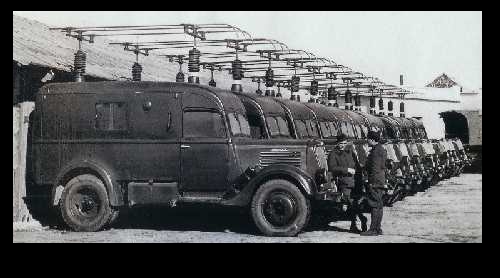
The following picture shows how a NVIS antenna beams straight upwards. It is called a cloud burner so that its signal goes straight up and comes straight back down over an area of several hundred miles. This is superb in locations like the mountains or in cities because nothing is going to block it. The signal will arrive at any antenna in the area. However, unless the recipient is also using a NVIS their response signal may skip out to anywhere and you will never know if they received your message because they will have no way of telling you. 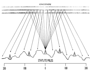
The other neat thing about the NVIS is that its source location is easily concealed. Since the NVIS signal goes straight up, the mounted military units were able to hide by driving down into a valley or elsewhere where the source of their signals couldn't be detected. An ideal for you could be in something like a sand pit whose high steep (at 90 degrees to each other) walls will block any signal coming off the sides. Anyone searching for the source of the signal with a range finder only knows that it is coming down from the clouds. They have no idea as to where from it is going up into the clouds. Even when installed around one's home the antenna is difficult to detect visually since it has a�very low profile. Traffic walking or driving by one's location will be less likely to see it, and it can be easily camouflaged, if needed,�without impeding its effectiveness! |