|
Radio Setup
The connection to the computer is very simple.
2. An "In" wire between the transceiver and the Sound Card 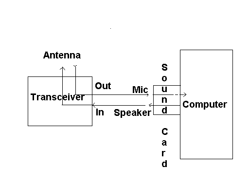
the SAFE EMS User Interface can interface with many transceiver models 1. The "Out" wire is the ONLY wire that you need if you are only going to receive and are not going to transmit. It is a wire between the transceiver and the computer that goes from the "OUT" jack of the transceiver and into the Microphone jack (usually pink colored - or you can plug it into the blue colored "line-in" jack) on the sound card in your computer. The received signal comes in from the Antenna to the transceiver and goes out of the transceiver into the computer. 2. If you are going to transmit, then you need a wire between the computer and the transceiver that goes from the output jack on the sound card in your computer (which is usually a green colored jack) that you then run to the "IN" jack on the transceiver. The transmitting signal comes from the computer and goes to the transceiver and then goes from the transceiver out over the antenna. 3. An ESSENTIAL step. WARNING! You must NOT have a microphone plugged into your computer when you are using the SAFE EMS software. This step is ESSENTIAL and the most complicated. You must make CERTAIN that NO OTHER sound inputs are connected to your computer. This means that no other devices such as MICROPHONES are connected either directly or from such devices as built-in web cams. This step is absolutely essential for the transceiver to work properly in the transmit mode. Additional Details:
TRANSMIT/Receive switch should be in Receive position when setting up. Details for setting signal strength will be covered under software discussion. The transceiver is shipped with only the receive mode enabled. In order to enable it for transmitting a jumper must be attached between points A & B on one of the printed circuit boards. Ford details see the schematics in the manual shipped with the transceiver. In on-catastrophic times and circumstances this can only be done legally by an Advanced Ham.
Using a regular Ham radio the dial was set to 3.850 USB.� The center frequency of the Spectrum Analyzer was set to 3.850 and the span was ~8khz. Using the SAFE transceiver, these are the values that you get by default. The first picture below shows the spectrum when the waterfall is set to 1000 on the SAFE EMS User Interface and the transmit button is activated. The RF signal on the Spectrum Analyser appears as 3.851 The least significant number in the above Spectrum Analyzer value is the MOST significant number on User Interface waterfall. (And in the frequency indicator on the User Interface control bar - and on the selected channel of the multichannel display.) In other words the "1" in 3.851 is the 1000 on the waterfall. 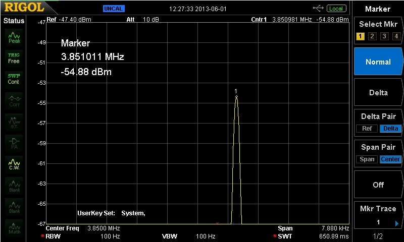
In the display below 3.851 has become 3.852 and the "2" in 3.852 is the 2000 on the waterfall. The point is that the numbers on the User Interface waterfall, and in the frequency indicator on the User Interface control bar - and on the selected channel of the multichannel display, are representing the least significant (the most refined measure) of the frequency choice on which one is transmitting or receiving. It is IMPORTANT to NOTE that the displayed frequencies may differ between the transmitting and the receiving stations. This is due to the fact that the accuracy of the displays is a function, among other things, of the quality and sensitivity of the circuitry. Our real world low cost transceiver will most likely differ from unit to unit in comparison to an accurate laboratory measuring device. In practice one operator may set their signal to transmit at 2000 and the other may receive and transmit showing a slightly higher or lower number on their display. If one is the controlling frequency then the other wants to keep a log of exactly where to look for them. While the controlling location may always send on the exact frequency as shown on its radio - the frequency on the receiving radio may show minor deviation from time to time due to atmospheric and other conditions. In practice, the receiving frequency will simply look for a signal in that area on its waterfall and its User Interface multi-channel display/selector. This is one reason that it is important for the transmitting station to repeatedly identify itself so that receiving stations will know that they are monitoring the station that they are intending to monitor. 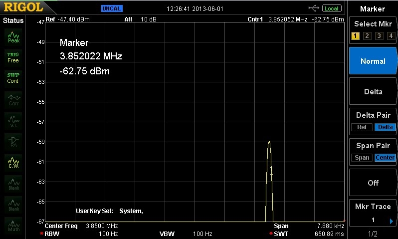
|