|
S.A.F.E. EMS Introduction
There is nothing in this section of the Help files, or this section of the manual, that one needs to know in order to operate the S.A.F.E. Emergency Messaging System. All the essential information as to setting up the system, providing power, creating a suitable antenna, as well as using the software is covered in separate sections of the Help Files and this manual. This Help file and section of the manual contains theoretical background and an overall view about the purpose, design, and underlying radio theory behind the S.A.F.E. Emergency Messaging System. This Help file is for those interested in delving into such underlying theory. - There is nothing essential within this Help file or manual section in regards to using or operating the S.A.F.E. system. S.A.F.E. Ham Net Mission Statements The S.A.F.E. Ham Net has two missions and a separate distinct way for approaching each mission. The S.A.F.E. system is uniquely designed as to both hardware and software to fulfill both of these missions for use with LERNs and TRIADs in the future, and for use with TRIADs now. Its unique design objective combines:
b. Unmatched reliable communication within 400 miles for an anticipated catastrophic circumstance. c. Simplicity of operation never seen before. The primary mission for the S.A.F.E. Ham Net is communication between groups within an expanded LERN (Local Economy Recovery Network). Such group networks cannot be setup or function until after the Great Catastrophe just as neither can the individual LERNs or the alternative currencies upon which they are based. The protocols for communication within such LERNs will need to be set up autonomously by each of the LERNs and LERN levels everywhere, although it is good beforehand to speculate on and discuss possible procedures. Mission Two (Secondary): The secondary mission for the S.A.F.E. Ham Net is communication by individuals within TRIADs. Communication within TRIADs can, and most often will, take place without the S.A.F.E. Ham Net but the TRIAD network is a simultaneous spontaneous non-designed structure intended to permeate and be supportive of (all three) the individual, the LERNs and the S.A.F.E. Ham Net. It is presently immediately implementable and eminently valuable for both introducing the concepts of TRIADs and LERNs and for any other desired purpose.
Emergency Communications for this Introduction Section A.
Mission Statement Two Emergency Communications Regulations and Laws Part II: Why we picked PSK31 on the 80m Band Part III: Why the Present Ham Systems Won't Work For S.A.F.E. Part IV: A Brief History of the S.A.F.E. Hardware Overview of the Documentation Sections The S.A.F.E. EMS (Emergency Messaging System) Net operates solely on the 80m band and in only the PSK31 mode. The documentation is presented in eleven sections listed in the following order on the S.A.F.E. EMS software HELP drop down menu and as Sections A-L in the printed manual):
A. S.A.F.E. EMS Introduction (this section) Why we picked PSK31 on the 80m Band Radio communication uses a part of the electromagnetic spectrum. Some parts of the spectrum are visible such as the light waves that we see with our eyes. Other parts are not visible to our eyes such as infrared and x-ray and radio waves. All parts of the spectrum consist of energy traveling in waves and we define the different parts electromagnetic spectrum by the wave lengths. The various parts of the radio portion of the electromagnetic spectrum are also defined by their wave length. By convention we designate these various radio portions as bands. Some of the radio bands of frequencies where amateurs are allowed to use PSK31 are:
One needs to distinguish the concepts between bands and frequencies. Looking at the above chart the band meters are describing the wave length. Therefore - a 10 meter band has a wave length of 10 meters - which in feet is about 33 feet long and an 80 meter band has a wave length 80 meters long which is approximately 262 feet in length. It is just a matter of converting meters to feet. If it were the convention we could say that the 80m band is the 262ft band. Just simply think of the beginning and end of a wire being that far apart. The next part of the concept is the frequency. Frequency is measured in Hertz (Hz), named after Heinrich Rudolf Hertz who was the first in 1886 to prove that radio transmissions move in waves. The most common measurement is that of a sine wave which measures the distance between the peak and trough of a wave. How many peaks and troughs occur between the measured distance are what we call the frequency. If there is only one peak and trough then the measurement is 1Hz and if there are a thousand peaks and troughs within the same distance then the frequency is 1000Hz or what we call one kilohertz (1kHz). You will see that we have selected from among the bands and frequencies listed the longest wave with the lowest frequency. There is actually available a 160m band but there are trade-offs in everything and we are already having to deal with a very long antenna and other considerations within the radio. This was the most reasonable for us, for a long slow reliable signal. The 80m band is comprised of frequencies from 3500-3600 kHz. PSK31 is assigned (or uses through convention) 3580kHz-3583kHz and the S.A.F.E. EMS transceiver centers on 3.580 MHz (close enough). We convert from Hertz to Megahertz by simply moving the decimal point. Mega means million so consequently 3.580 MHz and 3580 kHz are the identical same frequency. Properly written numerically the number would be 3,580,000 Hz, but confusingly to the novice the number is spoken of simply as 3580. The measure of the width of a signal across the frequencies is also measured in Hertz. The frequencies are a continuum across the electromagnetic spectrum. What we designate as a frequency is determined by the refinement of the radios to distinguish between them. PSK31 actually uses a very narrow bandwidth of frequency and thus permits about twenty simultaneous signals within the bandwidth required for a voice transmission. There are other widths that are sometimes used with PSK such as PSK64 or PSK128 or still wider in order to give more reliability to the signal. It was suggested to us that for our purposes that we use PSK64 but once again there are trade-offs. By using PSK31 within just a small one kHz slice of the single 80m band dozens of S.A.F.E. users will be able to operate simultaneously within each relatively small circle of six or seven hundred miles diameter which is our goal/ideal. (We state a lower practical standard of 400 miles.) In practice the S.A.F.E. Net could support thousands of users in any such geographic area because not everyone would be transmitting simultaneously (although everyone could listen simultaneously)and there would probably be also a broad time spectrum of distributed usage. The map below shows actual usage some years ago of the radio circuit designed by Skip Teller. The S.A.F.E. EMS transceiver is based upon the same circuit. The red circles indicate a 200-mile radius of solid contacts. The transceivers then only had a 3.5 watt power output whereas we have nearer a 20 watt power output combined with a number of other improvements. The effectiveness of the S.A.F.E. network will depend upon the number of participants. Nevertheless, this shows the concept of how the users will be interrelated. With a different antenna it is quite possible to communicate world-wide with the S.A.F.E. Transceiver but in that case there will be the usual problems of unreliability created by signal skip.
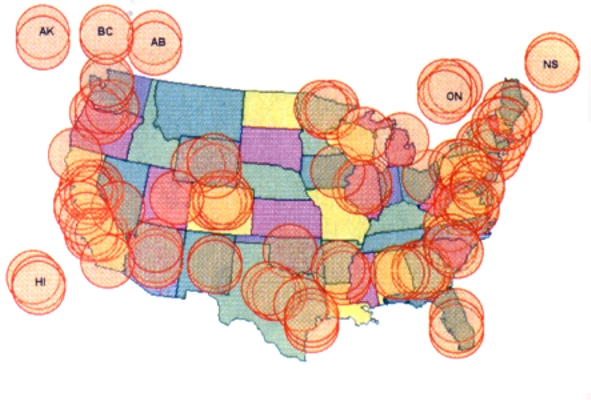
Map used by permission from:
Ideally the bandwidth of a single PSK31 signal is 10Hz. PSK31 derives its name from its baud rate (which is actually 31.25). Baud rate is the number of characters transmitted per second and a baudrate of 31.25 equates to approximately 50 words per minute, a substantial typing speed, and this means that the signal can keep up with someone typing at that speed if they are typing directly into the transmission stream. In practice we often pre-compose the message and then let the computer send it out.George N2APB and Dave Benson NN1G/K1SWL
In the design of the electronic circuitry the baud rate and the signal width often become intertwined and the PSK31 signal is often 31Hz wide, or even wider. The width of the signal can become very much broadened, and therefore detrimentally impacted, if it is combined with a voice signal and therefore it is of the UTMOST IMPORTANCE that NO microphone be active in the computer that is generating the sound wave being sent to the transceiver for transmitting. 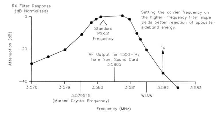
Chart used by permission from:
Besides the signal breadth there are many other factors that can affect the signal strength/clarity. Transmission power and solar/weather conditions are the two main factors but also terrain (which has relatively little effect on NVIS antennas) and ground conditions are among the many.George N2APB and Dave Benson NN1G/K1SWL There are various ways of handling/using a radio signal. The most basic is to 'make' and 'break' the continuous wave (CW). This was first used by Samuel Morse in 1844 with the invention of the telegraph over a wire and it was then duplicated / demonstrated by Guglielmo Marconi as wireless telegraphy in 1897 and for a century more it was a requirement that to become a radio operator or a Ham, one had to know Morse code. Recently this is no longer a requirement, even for advanced Hams (although it is still required of examiners). Still, the radio signal is processed on the same principles, of between a signal and no signal or two different signals of some sort. One method is called FSK which stands for Frequency Shift Keying. In this method the transmission shifts between frequencies, one frequency standing for mark, if you will, and the other for�space, or digital inverse state. Another method is that of PSK or Phase Shift Keying which is to say in which phase of the sine wave the signal is sent and this is the method that we use. Actually we use BPSK which stands for Basic PSK. The other choice is QPSK which is Quadrature PSK a method intended to increase reliability by having redundancy of shifts for error checking but which in practice has turned out to be less reliable. A further distinguishing/determining feature is whether one uses USB or LSB (Upper Side Band or Lower Side Band). General convention has been to use USB and while the design that we began with used LSB we have switched to USB. Every radio signal generates harmonics, which are associated frequencies above and below the designated frequency and it is here that the phase modulation is determined. In PSK31, on top of the phase shift of our chosen frequency we impose a rate (length of time) at which we choose to vary our signal and this is called the baud rate. The chosen baud rate for PSK31 was defined and set by Peter Martinez in 1998. He also chose a novel coding method called Varicode. Description of the details is beyond what we will cover here - but it is one the factors that leads to the high reliability of PSK31 and our system. All of these details are of no concern to the user of the S.A.F.E. EMS transceiver, because while a Ham operator using a full Ham rig has to consciously make all these choices, and has the flexibility to vary between them, the choices are all fixed and set within the S.A.F.E. EMS transceiver and the User Interface software.. The users of the S.A.F.E. EMS transceiver automatically gets 80m USB BPSK31 and the choices are all made for them. However, these were not only simplifications of the system, they are good choices and assure that all the users of our transceiver within the network are on the same side of the same band and are using the same baud rate. Otherwise they might never find each other. Once again - all this theory and detail are matters that you simply don't have to worry about. This lengthy explanation has been made to assure any who are concerned, that the choices of band, bandwidth, baud rate, transmission mode, combined with the reliability of the digital mode, were all carefully evaluated in consideration of the cost, power requirements, ease of use and necessitated antenna design for our particular application of an EMS. As stated by Wikipedia, "PSK31 can often overcome interference and poor propagation conditions in situations where voice or other data methods of communication fail." This reliability is further greatly enhanced by our antenna, hardware, and software designs. Why the Present Ham Emergency Systems Won't Work For S.A.F.E. The S.A.F.E. EMS (Emergency Messaging System) Net is quite different from existing Ham Emergency Nets such as ARES (Amateur Radio Emergency Service), ARRL (American Radio Relay League) or the many local nets to be found throughout the world. In fact, the concept behind the S.A.F.E. Net is quite different to the interest and practice of most Ham radio. Ham radio is a licensed system of radio amateurs that practice their art mainly as a hobby. The variety of specialties would be very lengthy to catalog but let it suffice to say that they examine and work with techniques for bouncing radio waves off everything imaginable from the Moon, satellites, lightening flashes, meteoroids, and other phenomena including very long ground waves. The goal of many Hams is to contact as great a variety of other Hams as they can and the classic picture of a Ham is one in his shack sitting in front of a wall plastered with QSL cards. In admiration you may ask - "Have you really talked to all these places?" "Yep." "Here is an interesting one - could you call it up again now?" Nope. No can do. And that is the nature of much of Ham practice. The reason is, that much of such Ham communication works largely on the basis of 'skip' which involves ever changing atmospheric conditions. How in the world then can Ham emergency systems work? Well, the key is that a Ham in the disaster area 'skips' out and is received by a Ham somewhere. That Ham then relays the message by other conventional means to the intended party or obtains information and relays it back. In this way Ham emergency systems can function when all or most other local means of communication are not. Many Hams do communicate reliably locally, using what are called repeaters. It is highly unlikely, because of EMP and lack of continuing power, that any of the latter will be available in the event of the kind of catastrophe that we are anticipating. None of the current Ham practices apply to the global catastrophic situation for which we are preparing. There will be no other conventional means to 'skip out' to. Nor will many of the other Ham capabilities, such as the use of repeaters, store and forward packets, beacons, or satellites be available. We are developing a system for when there is no electricity, no other forms of communication such as cell phone, phone land lines, TV, radio, etc., etc., etc. Most Hams have no more interest in such a scenario than does the general public. They will immediately tell you about EMP hardened emergency transmitters and repeaters, uninterruptable power supplies with backup generators, Faraday Cage protected systems, COG (Continuity of Government) programs, and a plethora of other such supposed remedies. Those inclined towards the S.A.F.E. program trust none of this and they especially do not trust that such systems/remedies will be available to service their personal needs. While not particularly sympathetic to such a universal catastrophe there are many Hams that will offer alternatives to the S.A.F.E. EMS Net. For example, Citizen Band radios - particularly when modified in certain ways to expand their range, or inexpensive handheld transceivers available to entry level Ham licensees. And of course there is the old reliable standby of CW/Morse Code. In fact there are available such a variety of solutions that it would cause dizziness just to try to alertly hear a complete recitation of all their acronyms. And most, or a great many of them have their enamored advocates. So the question must surely be - why do we need one more? The answer is - because none of them are designed for surviving nuclear WW3 or some equally immense or surpassing universal catastrophe, for which we are preparing. Many a prepper has determined to get a Ham license, and I would certainly not discourage anyone from doing so. In point of fact the S.A.F.E. EMS will work with any full blown Ham rig, and all such Ham operators are fully capable of communicating with the S.A.F.E. EMS, if they wish to make the effort (such as installing the proper antenna) to do so. It is really not that much effort, but it is usually just different from the interests of Hams. So, now that I have explained the reason the S.A.F.E. EMS is needed, let me explain how our system was developed. A Brief History of the S.A.F.E. Hardware A full blown Ham Rig will cost around $1500 just for the radio and many Hams spend much more on just the radio, antennas and ancillary equipment. It is not unusual for a dedicated Ham to have tens of thousands of dollars invested in their systems, and yet most often it will not meet our needs just because of its elaborateness. Our goal is to provide an inexpensive radio, including the antenna, that will cost less than $200 and serve our particular need for simplified dependable two way communication within a three to four hundred mile range. To do this we limit ourselves to one band and one type of antenna. Our initial design is based upon the proven design which was developed by Skip Teller and which has been used by hundreds of QRP (low power) users. With this build-it-yourself radio users have often been able to contact other Hams hundreds, sometimes thousands of miles away and it was very popular with many clubs. Kits were sold by a firm from which we tried to buy up their surplus inventory when they quit distribution, but they were not willing to sell them to us because they planned to redesign and go back in the business - something which they never did. Their reason for a planned redesign was that quite a number of people trying to assemble the kits were unsuccessful in tuning them, but this was something we would have avoided by having the radios factory built and tuned. Since we were not able to obtain the remaining inventory or production masters from the previous manufacturer, we set out to redesign and improve the radio ourselves. In any design, some deficiencies or relative weaknesses eventually become apparent and a redesign can eliminate those. The power design for the Warbler was 10 watts but its effective performance was more like three and a half which its enthusiasts felt was quite adequate. A second unrelated manufacturer had discontinued production of an 80m 20 watt amplifier, once again a well proven design, but demand was lacking because of custom and usage regarding that band. We took both these designs as well as a third provided by another source and obtained engineering to integrate them into a totally new layout so that there could be no accusation of our pirating the work that had gone before us. In addition we have adhered to a number of standards specific to our particular needs. We have made the printed circuit boards thicker than is current practice in the present mass production, lowest possible cost, planned obsolescent, disposable society. We have decreased the board population density and increased the width and thickness of the printed runs so as to increase reliability and reduce mutual RF interference. We have provided plated-through holes for easy repair should it become necessary, in addition to the pads for automatic component insertion for mass production. All of this to create an exceptionally durable device to be shipped to the end user in a Faraday cage. Equally important to the hardware was a tailored software design. Once again we found a reliable widely used and proven public domain system that we could modify. It was a very arduous task for our programmer and analyst because the program contained over 1300 variables that could be chosen and possibly confused by the user. We narrowed this down to less than twenty, most of these having defaults, to simplify the user interface. It was through efforts such as this and the selection and design of the antenna that we have created a system that we think is by far the best suited to our need - of any of which we are aware. |