|
The making of the Källe-gasifier
By Torsten Källe
January/February 1942
(Translation to English
2000, Joacim Persson <[email protected]>)
PrefaceTorsten Källe's charcoal gasifier was somewhat ahead of its
time. It was very popular due to its easy maintenance and fuel economy. Some
features with this gasifier is perhaps recognised in modern gasification
technology; among many things it was a sort of predecessor to what today is
called `circulating fluidised bed.' Charcoal gasifiers were generally more
popular than wood gasifiers during the producer gas era in Sweden in the days of
WW2, even as the wood gasifiers improved in design. Wood gas was cheaper by all
means, but charcoal gasifiers were so much easier to handle.
This article
perhaps belongs in the historical section, but I feel it is worth reading even
today. I for one find Mr Källe's reasoning and experimenting very
inspiring.
This article is shamelessly stolen from the Royal Swedish
Academy of Engineering's publication Teknisk Tidskrift, namely from the
issues as of the 17th January (pp.4--8) and 21st February (pp. 15--16), 1942, in
the Automobil och Motorteknik section. (Also published earlier in a
publication named Fläkten, unknown date). Enjoy!
Joacim
Persson
The making of
the Källe-gasifierOver a year ago, when I started
using a producer gas-powered car I just had bought, I was both impressed and
excited; imagine it being even possible to, by such simple means as charcoal and
air in a fairly air-tight tin can equipped with a grate at the bottom, a pipe
where air were blowing in, plus hatches and lids, be able to produce fuel for
such a choosy machine as a modern petrol motor! It all reminded more of a
kitchen stove, and seemed in its primitive simpleness really amazing. Obviously,
vast fields were open for speculation.
While I was starting and driving
with this device, taking off slag and soot, and topping it up with charcoal, I
subconsciously made certain observations, and one day I caught myself engulfed
in experimentation, trying to get something more out of my
gasifier.
Apart from the reoccuring event of taking out the slag, the car
was nice for long drives. But it was also my opinion that it ought to be
possible to improve its accessibility. In other words: make it start easier and
faster from cold condition or after a longer pause in the driving. What more
precisely gave me the impulse of this possibility was that when the gasifier was
freshly de-slagged and serviced, thus new fresh charcoals were in place in front
of the nozzle, the car started significantly faster, maybe in just 5 minutes
rather than the normal 10--15 minutes for a car that has cooled down. So I begun
studying the reasons for this. The explanation was simple. The fresher, ash-free
and cleaner surfaces were more reactive. I also found out that the size of the
fuel were of great importance; particularly if the smaller charcoals had clean
(new) fractures; a certain amount of moisture also appeared to be
beneficial.
As gasifiers in general are made with the nozzle in fixed
position somewhere in the combustion zone above the grate, a cavity appears in
front of the nozzle when air rushes in and oxidises the charcoals in its way;
this cavity is then prevented from being filled out more or less due to bridging
in the fuel. This becomes even more obvious when the gasifier is turned off,
when vibrations and such are no longer contributing to the filling out of the
cavity. So the next time the gasifier is lit, there is a cavity in the
charcoals, and a gasifier-match1 dropped down will lit the charcoal more or less
distant from the mouth of the air inlet, resulting in a slower start. This also
explains why, as we all know, it is so much easier to start the gasifier if you
stir around in it first.
Firing up was even faster if the cavity in front
of the nozzle was filled with finely crushed charcoal, filled in through the
primary air inlet. The explanation for this is that the charcoals in that case
has, compared to its volume, a very large surface. One thus had to lit up a
smaller mass of charcoal than with coarser chars, to gain enough reacting
surface and thereby get enough gas generated for starting the motor
on.
By putting fine charcoal in front of the nozzle in the cavity formed
when the gasifier cooled down, I now had pressed the starting time down to 30
seconds.
To avoid having to bring two kinds of fuel with me on my
journeys; one for firing up, one for driving, I made the nozzle movable. By a
simple motion it could be loosened from the outside and with a guider and handle
be thrust in and out, so the charcoals in front of the nozzle be crushed.
Thereby I allways got charcoals with fresh fractures, and immediately after
lighting it with a gasifier match, a small reaction-zone, whose reacting surface
were enough to generate starting gas for the motor. When the motor was started
and its greater sucking power doing its work, the heat quickly spread in the
hearth, and the motor speed could soon be increased further.
This implied
a great improvement, and the accessibility of the car had increased
significantly.
After this minor success, I started working in laboratory
scale; above all there was one discovery I wished to take a closer look at:
the uneven generation of gas, which appeared most wilfully during
driving. After a few dozen kilometers the motor could suddenly become weaker and
weaker and just as suddenly regain its normal power. Normally, though, the power
continued to decrease.
The main suspect was the large grate. What
guarantees were there really that the gas would distribute itself evenly across
the entire mass of charcoal by a grate as big as 300--500 mm Ø , i.e.
all gas really be reduced? It could easily be, that the gas according to the law
of least resistance sought itself channels through the charcoal, where it was
less packed with charcoal dust. In those areas the gas velocity would increase,
the reaction more vivid, which in turn decrease the resistance of flow even
further.
Yes, why wouldn't the air from the nozzle even burn itself a
channel all the way down to the grate, by which the reacting surfaces became far
to small and the amounts of nitrogen and CO2
increasing catastrophically. All these extremes were plausible.
My
suspicions were confirmed during night-driving. The outer cover of the gasifier
showed vaguely red hot spots, whose position varied under way and most
irregularly reappeared here and there.
Enough proof! It was quite
obvious. The most important part of the reaction process was more or less left
to coincidence. To make it efficient it had to be fixed in precalculated paths.
It was also fairly clear in what way this was going to be achieved.
In
the same manner as when the primary air left the air pipe at a narrow section,
around which the relatively modest oxidation zone were formed, the several times
larger reduction zone must also be fixed against a narrowed section, namely by
the outlet for the ready gas, i.e. the grate.
This must be shrinked down
to a minimum. That was, however, not possible with regular design
principles.
There was more to it. The sizes of the fuel must be decrease.
I already had gotten a taste of what that implied to the start-up
properties.
By simple mathematics it was clear that the size of the
charcoals and the reacting volume were in a linear dependence upon one another,
e.g. if the size of the charcoals was decreased 6 times, the necessary reacting
volume would also decrease 6 times.
On basis on this reasoning and from
tangible proof, I came up with the idea for the so called central tube, which
eventually grew out to a whole new principle of operation for gasifiers, and it
is this principle I now will try to briefly explain.
The figures 1--4
illustrates four different phases in the chain of development. Figure 1 shows a
regular type of charcoal gasifier with downdraft combustion and equipped with
the already mentioned movable air tube, with which one during start-up can crush
the charcoals at the reaction zone. The latter was carried out in the manner
that one loosened the handle (1) from its bayonet lock, had two or three thrusts
at it, and then locked the handle again. When the gasifier match was dropped
down through the air inlet there were a sufficiently amount of fresh surfaces to
lit at, and produce a sufficient amount of gas.
Figure 1: Ordinary charcoal gasifier, with
a movable nozzle added to it.
Figure 2: A first outline.
In figure 2 the
guiding tube has been extended all the way down into the fuel, and also been
combined with an exhaust pipe (1) for the gas. A seemingly insignificant change,
but yet a radically new way of operation! The grate became obsolete, as also the
stove. This laboratory speculation was never tried in a car however, as it
immediately apparent that due to the high gas velocities at the mouth of the
outlet, a far too great amount of coal dust would be sucked up along with the
generated gas.
Figure 3: The first experiment with the
grid.
This nuisance was eliminated as in figure 3, by
introducing a grid which let the gas through, but blocked out at least the
larger particles. It was really at this stage that the experimenting first could
be carried out under more practical circumstances of operation. It was now
possible to try out finer and finer selections of charcoal. It was found,
however, that it was necessary to sort out the dust from the fuel, at least if
there were larger amounts of it.
The operation is thus, that the charcoal
particles are sucked onto the grate (which I hereafter will call the `grid') and
with that as centre, build up a more or less extended ball of charcoal, through
whose porous walls the gas may pass. If the chars contains a too large amount of
finer particles along with dust, the ball of coal can easily become too dense
and offer a resistance that is far to great for the gas to penetrate it to the
grid.
This was of course a problem, and eventually brought forward the
final solution, as shown in figure 4.
Figure 4: Moveable grid, connected to a
membrane and spring.
The grid (1) is here fixed to the lower part of air tube (2), while
the upper part of the air tube is fastened to the membrane (3) in the membrane
case (4). The guiding tube (6) is a little wider, so that the grid can slide in
and out from the mouth. A spring coil (5) presses the membrane and the air tube
upwards, and by that the grid is fully covered by the guiding tube. The device
operates in the following manner:
If the motor for example needs more
gas, the suck effect at the grid opening increases, the pressure drops in the
gasifier and more air flows in by the air tube. The lower pressure in turn
affects the rubber membrane, which bends downwards and thus also moves nozzle
and grid downwards. The result is that the reaction zone as well as the grid
opening is increased. If the motor sucks less gas, the membrane is moved upwards
in the corresponding way, as the vacuum in the generator decrease, by the spring
(5) and the reaction zone as well as the grid opening decreases. In other words:
the generator has become self-adjusting, not only according to variations in
gas consumption from the one and same motor, but also adjusting itself to motors
of varying size!
During normal operation the consumption of gas
undergoes reoccuring variations depending upon how the road and traffic varies
ahead. The membrane will thus constantly alter its position, and so will the
grid. These variations is exploited by the gasifier for scraping the grid clean
and thereby prevent it from clobbering up. Every time the driver takes his foot
off the throttle, the grid slides into the guider tube and eventual coal
particles are scraped off. When the driver again presses down the pedal, the
grid automatically slides out as much as decided by the vacuum and the motor
speed. The mass of charcoal at the grid is hereby broken up and made porous, so
that it lets the gas through without too much resistance. By this even the
finest charcoal particles were useful, even if they were severely mixed with
char dust. By the moving grid a few other interesting conditions appeared, which
I will get back to later.
Due to the central placement of the grid and
the nozzle the reaction zones becomes fully separated from the walls of the fuel
container, and the fuel itself will thus make an efficient insulation. By the
constant grinding of the charcoals the reacting volume is gradually decreased,
and so a quite concentrated reaction zone is formed, while at the same time the
more compact fuel further prevents heat losses by convection.
At this
point, however, a tremendous excess of heat appeared in the gasifier, i.e. the
generated net heat was more than what was necessary to convert all of the air to
producer gas. The excess heat resulted in such a steep increase in temperature
that the nozzles melted down in just a few minutes.
We now had to
eliminate this excess heat, but preferably in some way that the heat was made
useful. As so many times before, an opportunity was given to make a virtue of
necessity!
One could say, that the carbon-dioxide (CO 2 ) is the `fuel' from which producer gas, that is carbon
monoxide (CO) is made. It could thus be considered a pure waste to generate
carbondioxide from charcoal, when the former ---as the final product of
combustion in the motor---is available in sufficient quantities from the exhaust
gases! It also goes without saying, that the larger portion of the CO 2 in the exhaust that can be reused for producing
carbonmonoxide, the more economically the gasifier operates, and the longer one
can drive on the same amount of charcoal, and the cheaper the driving
is.
I therefore decided to mix a certain portion of the exhaust gases
from the motor into the primary air. The combustion gases, passing from the
combustion zone to the reduction zone will thereby contain more carbondioxide
than what corresponds to the consumed charcoal. The excess of heat will be
consumed for reducing the excess CO 2 . If the
portion of exhaust gases is small, the reaction will become complete and the
producer gas becomes entirely free from CO 2 . In
practice it is however better to let the producer gas contain one or two percent
CO 2 . The heat value of the gas will not be
significantly lowered by it, but it guarantees that all the heat is made
useful.
Further experiments showed, that the best effect was gained
by an adding of about 17% CO 2 to the gasifier, which, under the
condition that all of that was turned into CO, results in a significant
saving of charcoal.
The temperature in the oxidation zone is in this
way automatically regulated down to 1000°--900°C, and I can mention that it
keeps itself remarkably constant around that even for different loads.
Naturally, this is so because the CO 2 is added
proportionally to the need for primary air.
I now get to the third phase
in the development. By the constant moving of the grid and the nozzle, an
interesting phenomenon could be observed. As mentioned earlier, the charcoal
particles is scraped off from the grid, and thereby fed into the oxidation zone
below it. Here they are caught by the jet from the nozzle, whereby their surface
temperature is quickly raised, while at the same time they are caught on by the
circulating flow of gas. Some of it is stuck on the grid again while others
returns to the circulation, until they have more or less completely been
gasified. In fact, most of the mass of charcoal that is active in the reaction
is in constant motion inside a cavity, which automatically alters its shape and
size according to the velocity of the gas. When the need for gas for instance
increases and the grid along with the nozzle penetrates deeper into the
charcoal, the nozzle fumes up more char, which also is set in motion. A large
portion of this is sucked onto the exposed surface of the grid, where thus a
tremendously efficient reduction zone is formed as the reactivity of these chars
reaches an optimum. The slag dust which is generated during the combustion of
these clean-blown charcoals, together with the finer charcoal particles goes
along with the gas, and was for a start caught up by a plain cyclone
cleaner.
Because of the motion of the grid it was quite a lot of charcoal
which in this manner was sucked along with the gas, and it added up to
relatively large quantities of of useable fuel that thereby was separated in the
cyclone purifier. Most of this could by all means be put back in the gasifier
and prevent loss of fuel, but the trouble and risks with the highly flammable
and sooty cyclone dust remained.
So it was logical to try to return the
charcoal particles and dust to the gasifier continuously, and preferably to its
oxidation zone, to thereby get them back in the process again.
The
recirculation of CO 2 from the motor was already
in operation, and since the exhaust gases leaves with a certain pressure it was
obvious that they could be used for transporting the charcoal particles
back!
So we came to the design we can see in figure 5.
Figure 5: The final Källe-gasifier,
complete with wind sieve.
This device, or the so called wind sieve, is in principle
designed as an ordinary cyclone. The flow of gas enters tangentially into a
mostly cylindrical container, where it flows i circulation from the perimeter
and inwards. The exhaust opening is placed centrally by the upper gable plate.
During the circulation, heavy particles are thrown outwards against the
cylindrical mantle and sinks down to the bottom. The bottom is cone-shaped to
collect the separated material. By proper dimensioning of the wind sieve one can
limit the centrifugal effect so that only the largest particles, consisting of
uncombusted charcoal, is separated. The smaller particles consists mostly of
ashes and follows the gas to the filter.
The separated material is
returned to the gasifier in the following way: The return gas from the exhaust
pipe was lead in a tube straight through the wind sieve. In the lower part of
it, an injector is mounted, in which the return gas catches the charcoal powder
separated in the wind sieve. This is then blown back into the gasifier through
the primary air inlet, and the combustion zone is thus somewhat fuelled by
charcoal powder. The wind sieve with its accompanied recycling device is fully
automatic and craves no maintenance whatsoever. Parts of the dirty and risky
work with regular gasifiers have thereby been eliminated.
To gain
enough pressure for this transport the CO 2 is
taken from the exhaust pipe with a so called catcher, a sort of
pitot-resembling device, which turns the velocity energy of the exhaust gases
into a for the purpose fully sufficient static pressure.
That the mini
charcoals circulates during the reaction process is of course highly
interesting, and must be of great importance for the dynamics of the gasifier,
or its capability to quickly adapt according to the operating conditions on the
road. There is also ongoing research to closer seek out the above condition and
what really is going on in the reaction zones.
I imagine that each time
the char particles are caught by the primary air flow, a hasty oxidation of the
particles surface takes place. Since the heat conducting parameter for the
particle is very small, the reacting surface can be approximated to have a heat
capacity of zero, why the increase in temperature also becomes exceedingly
steep. During the next fraction of a second, the particle is bathing in its own
atmosphere of CO 2 , and the reduction to CO is
in full operation, whereupon the temperature hastily decreases. While the
particle is levitating in this manner, the surface is however kept free from
ash, so the purified carbons' catalytic effect becomes highly efficient and the
reduction benefits greatly from that, so that it can be kept up even at low
temperature.
The circulation of the particles also contributes to
automatically keep the gasifier free from slag. Naturally under the
condition that this is not brought to it in the form of pebbles, earth and even
nails, which has happened. The very fine slag powder, which originally is inside
the charcoal in the form of salts, is blown out through the grid, passes the
wind sieve, and finally is caught by the filter. If one could receive completely
pure charcoal without strangers (mechanically mixed-in pollution), the
gasifier would never need to have slag to carry out manually. Even at the
present, with our primitive production of charcoal, one can, if one handles the
gasifier properly, drive 2000--3000km without noticing any decrease in gas
production or increased resistance in from grid!
I have here
discussed the levels of slag in the charcoal. There is however another matter
connected to the charification work that calls for attention, that being the
charcoal content of so called vaporous parts, to which also tar is
counted!
I would really like to meet the gasifier driver who never
have been crossed over what he has felt was `the bad job of the gasifier
designer.' Because it is allways the designer that is blamed if tar occurs, and
I won't defend him in this matter. On the contrary!
The problem
with tar, should in my opinion almost be one of the basis of gasifier design,
because producing charcoal completely free from tar is practically impossible,
in any case irrational, and where tar occurs in the gasifier it is the
dominating problem. The whole issue of wood or charcoal gas with all the
existing mixed designs is, if one takes a closer look at it, very complicated
and filled with considerations and compromises, which by no means makes the task
of the designer easier.
An irremissible requirement is, that the gasifier
more than well must be able to take care of, and crack the quantities of tars
that occurs as maximum in prime quality charcoal. This limit is set by the
Governments Fuel Comission's norms for solid fuel vehicle fuels to circa
15 % glow loss.
But note well, that this must be fulfilled not only
under fully forced long drives, but also during shorter trips as for instance
cab driving.
What possibilities does this gasifier have then, compared to
other charcoal gasifiers, to handle such impurities in the fuel?
The only
way to neutralise these distillation products is to put them in contact with the
glowing or reactive mass of charcoal. Hereby they are cracked down depending
upon their kind more or less easily into products that improves the gas in the
form of CO and hydrogen.
The figures6--9 show a
schematic comparison, how these conditions appears in a common gasifier with
horizontal combustion, and in the gasifier described herein.
Figure 6: Regular charcoal gasifier
operating at low power.
Figure 7: Same as in fig. 6, now
on full power.
If we first look at figure 6 and 7; these
illustrates horizontal combustion in varying load. Figure 6 show us
how one believe the reaction zone looks like at start and slow driving. The
reaction zones cannot extend themselves to cover the whole large surface of the
grate, but this is covered with charcoal that doesn't reach reaction
temperature.
Because of the large differences in temperature that rules
inside a gasifier, a spontaneous circulation of gas and distillation products
occurs, emanating from the region where the temperature is the highest, there
the gas rises straight up; whereafter it is cooled down and sinks back along the
colder surfaces or its outer walls.
From figure 6 we can
clearly see that distillation products along with water vapour without hindrance
can pass through the grate during start and low load, without having been in
contact with reactive charcoals. In figure 7, where
the load is full, the conditions are better.
Figure 8: Källe-gasifier at low load.
Figure 9: ...and at high load.
Figures 8 and 9 displays
a cross section of the new gasifier design under the same conditions. The
difference in path of circulation is apparent. Since the grid and the nozzle at
low loads are retracted to the guider tube, the now insignificant grid surface
is covered with reactive charcoal, and there are no paths for the gas to go past
the grid on its way out. In addition the circulation is more pronounced and has
a different pattern in this gasifier. The maximum temperature is in this
gasifier concentrated to the central tube and the fact that it in its full
extent becomes hot, participates in leading the circulation into the right ways.
The rising stream of gas in the centre sinks eventually down along the perimeter
of the gasifier and is forced to pass through the oxidation zone, where thus
even the heavier tars can be cracked completely. The pattern is the same at full
force. Then the nozzle and grid slides out from the guider tube. The grate
surface becomes larger but has good opportunities to to constantly be covered by
reactive charcoal, and the circulation remains the same.
That the
circulation really goes on in this manner and is a part of the gasifier's normal
way of operation has been proved by applying screens upon the central tube to
prevent the circulation, and also on the inner walls of the gasifier to lead off
the gas flow and force it directly towards the grid. If one attempts to disturb
the normal circulation in this manner, the gasifier becomes significantly more
vulnerable to tar formation.
Finally one can ask oneself: what does the
design look like today, after being subject of industrial manufacturing, how has
it been made out in practice, what does it look like, has it lived up to the
expectations etc. I shall briefly touch that side of the matter as
well.
What demands should one have on an automobile
gasifier?
Primary I feel, that it should be designed for front
mounting, because the advantages with this are so apparent:
- It requires no permanent changes to chassis or bodywork.
- It leaves the boot free.
- It provides best possible balance to the car. If the fuel is brought along
in the boot, the weight distribution at the front and to the rear are about
the same.
- It is logical to place the gasifier as close to the motor as possible,
since it practically speaking is a part of it---and by that the piping, and
thereby the mounting, becomes as simple as possible.
I considered
these four pros of front mounting so strong that I choose that without
hesitation.
I now set up the following four conditions as a requirement
for making front mounting realisable.
- The gasifier must admit free view from the driver's seat. Therefore the
height must be small.
- Weight must not exceed 40kg.
- Radius of operation should be 100km for regularly sized cars (3--4 litres
cars)
- Considering the appearance, the gasifier should be possible to paint using
the same paint as for the rest of the car. Thus surface temperature must be
low.
If I, finally, present an oversight of the results, that indeed
has been reached, one shall find that the outlined requirements have been fairly
achieved.
- The view if perfectly clear---and yet the driver can, because of the
moving indicator, constantly monitor the gasifier with his eyes.
- The gasifier weighs 50 kg now, by all means, including cooler and
filter---but if raw material becomes available so that certain details, as
planned, can be made of light metal, the outlined requirement of 40 kg
may easily be met.
- A radius of operation of 150km per filling is not uncommon for smaller
cars.
- The exterior has been possible to make elegant, thanks to lean proportions
and a consequently streamlined design.
- The issue of keeping the surface temperature so low that regular car paint
won't take damage is yet to be solved. The original plan was that it should be
possible to let the fuel burn down completely between the fillings, until the
motor stalled by itself on the road. This can actually be done with this
gasifier without running any risk of damaging inner parts. But when this
happens the surface temperature becomes so high the paintwork may take damage!
- The accessibility is high---due to the quick start. Correctly maintained,
the gasifier can be started from cold condition in 30 seconds. It can stand
6--7 hours without having to be lighten again.
- Fuel economy is just as good as for petrol2. Due to the recycling of char dust and exhaust gases
and the fact that idling is not allowed, the fuel consumption has been taken
down to a minimum. I calculate that even a cab driver by this can save in more
than 50% of the fuel.
- The dynamics of the gasifier is excellent, thanks to the varying grate
(the grid), which automatically adapts the position and extent of the reaction
zone to the driving conditions. This also implies that the same gasifier can
be used for any car with a motor power of between 40 and 95 hp.
- The gasifier is self-cleansing within reasonable limits. If charcoal with
normal levels of char is used, one can drive 2000--3000km without having to
take out slag manually.
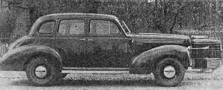
Figure 10: Automobile with a front mounted
Källe-gasifier.
By this I hope I have given an at least fairly clear description of
my gasifier, how it was invented and designed, and what it can do in
practice.
- 1
- They had special matches for lighting gasifiers in those days. The matches
were larger than regular matches, and had a much longer fuse. (translator's
note)
- 2
- Those were the days. Today, with European petrol prices anyway, even
charcoal gasifier powered cars would be much cheaper to drive than on petrol
powered such. (JP 2000)
This document was translated from LATEX
by HEVEA.
|