In today's How-To, we're still pimping out our dremel tool with parts
from old printers. In
Part
1 we got started with the controller and covered all the basics.
Today we'll get into the details and get busy with the power tools. And
that, of course, is always the best part.
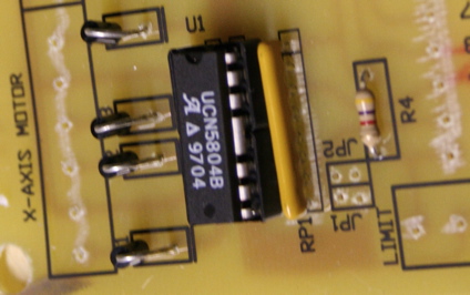
Once the board is finished, building the controller is pretty easy. We
highly recommend using sockets for mounting the 5804 chips. The thin,
flexible legs are much easier to fit into a hand-drilled board. (We were
out of 16 pin sockets, so we used pairs of 8 pin sockets.) The rest of
the board is standard fare.
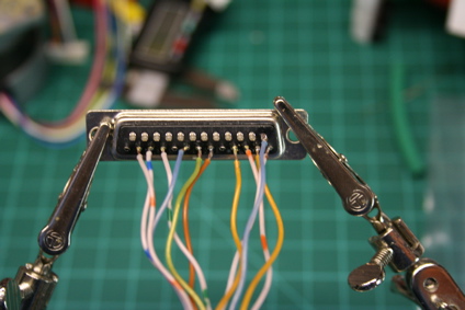
The controller is designed to connect to the parallel port, and each
connection is helpfully labeled with the pin of the Sub-D 25 connector.
We prefer the solder type connectors. Assembly is quick and easy if you
have a set of "helping hands" alligator clips.
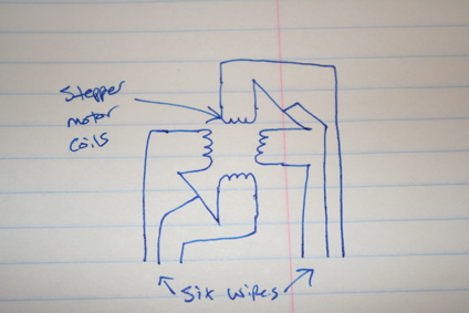
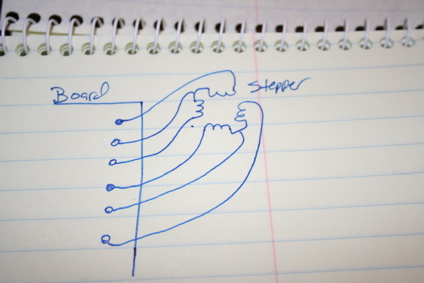
Electrically, unipolar stepper motors have four coils inside. Every
motor we've salvaged has had six wires, so we'll go over that type. To
have six connections, each pair of coils has a common lead, while the
opposite end has a dedicated lead.
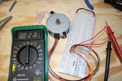
Identify the wires by measuring the resistance between the leads with a
multi-meter. If the wire are connected to separate sets of coils, the
resistance will be very high. Resistance across two coils will be double
the resistance of just one coil. On some motors, the common leads are
connected.
Each axis of the stepper controller has six output connections. Each
group of three wires connects to a pair of coils.
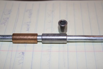
Linear slides are key to the design of a functional machine. These
slides are a half successful experiment. We used 1/4-inch steel rod from
the hardware store and some brass and steel bushings. The brass
material slides easier, but ultimately we think the smaller size and
unfinished rod is too prone to binding. Alignment is critical, but they
can work well for very short travel.
Salvaging matching rods from old printers is more optimal. Imagewriter
IIs have metal carriages with pressed in brass bearings. The cast
material is on the brittle side, but some careful dremel work can really
pay off.
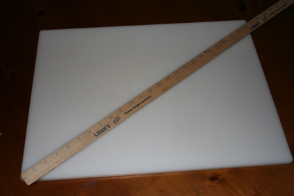
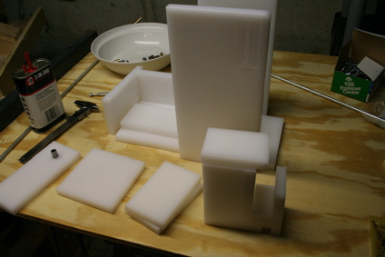
Getting appropriate materials for the project can be a challenge. In
this case, we're using two of these handy half inch thick cutting boards
from
Sam's Club. They're about
$10 each. Higher quality plastics like delrin can be obtained from
suppliers like
McMaster-Carr.
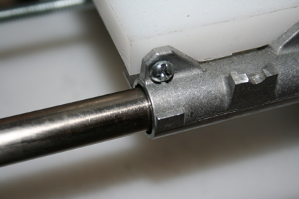
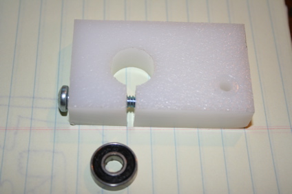
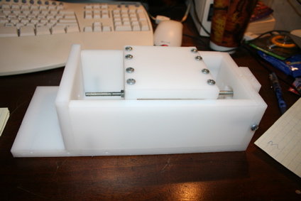
The threaded rod needs to spin freely with the motor, but still needs to
be anchored. We picked up a 1/4-inch inner diameter ball bearings off
of ebay. We drilled a hole the same size as the bearing, then cut a
slot in the piece with a miter saw. Finally, we drilled a hole for a
machine screw.
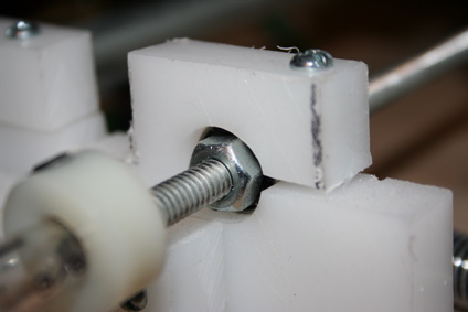
The bearing is sandwiched between two nuts on the threaded rod. They are
tightened with two wrenches. Then the bearing is inserted into the
block and the machine screw is tightened down. It's a simple and
effective design. We usually put one at each end of the threaded rod.
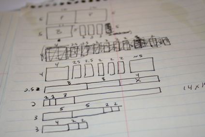
To build the mechanical base of the machine, it's important to put in
some design time. Determine how much material you have, draw out your
design and estimate how much material you'll need to achieve the size of
machine you're going for.
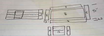
Spend time laying out each axis. Then break it into its components so
you can begin laying out your cut sheets. This was our original layout
for the first axis of our machine.
We cut our cutting boards using a standard table saw and a circular
miter saw. If the blade is sharp, you'll end up with some very nicely
finished edges.
The first axis for this table is simple. The base acts as a large
channel for the table. We've found that the plastic is soft enough that
it doesn't have to be tapped for threads. Just drill the hole with the
same bit you'd use if you were tapping threads (like a #21 for 3/16
threads) and bevel the outer edge a bit. Machine screws will thread
right into the plastic, and the threads will hold surprisingly well.
However, tapping the threads for extra precision isn't a bad idea.
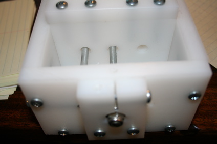
Originally
we wanted to use two 1/4-inch rods to maintain alignment, but thanks to
the channel design, just one was sufficient. The second rod was a
source of binding. We suggest incorporating a larger rod or two from a
printer.
The holes for the rods and screw were drilled at one time on the drill
press before assembly. The bearing block was added once the screw was
aligned. The locknut isn't necessary. If you want to hand align the
machine, This is a good place to add a knob or wheel to spin.
Next
week we'll build the rest of the machine, mount the tooling and finish
the job. See you then!


 posted Jul 4th 2006 9:37PM


Perfect. Nocomment!
Tons more CNC related Information here if you are interested:
http://www.cncinformation.com
Ivan
have you all seen http://hackaday.com or http://buildyourcnc.com they have great diy resources, or http://www.thomasnet.com/products/cnc-machining-45330503-1.html, to get your parts, and your off!
wow, I can't belive this is still going (well I can). Much more helpful then that ipod dock.
One suggestion for people going to try this themselves, the following store has basicly anything you could want, and its all good quality, get your bearings here, maybe some decent plasic or aluminium if you want:
http://www.mcmaster.com/
Other then that this is really growing on me. I wonder if you could get something like this to give you a 10*10 cutting area, maybe a manual Z axis?
What is a CNC machine?
cnc machine!!
how to learn more for cnc machine specially plastice machine?
how to learn more for the programe for cnc machine?
What is a CNC machine?
http://en.wikipedia.org/wiki/CNC
For some of the components it might be worthwhile checking out www.emachineshop.com. The even have a CAD program provided gratis. They do one-off or small run as well as production runs. Check it out. It really is cool to have this sort of thing available to the average Joe. For PC board there is www.PAD2Pad.com that will do custom boards. They also provide design tools!
also if yuo would like to build a bigger machine check out cnczone.com
thanks guys, this is an awsome tutorial. iv always wanted to build one for modeling but have little experties in electronics so connecting the motors to the comp was a problem. For mine, to negate all that xonstruction work of the x and y axies, i used 2 old scanners and just mounted them atop each other.
thanks a mill for making such an easy tut that most ppl with a need for this maching could build it
nice job, much apreciated
And when you have finished building the CNC machine go over to www.woodenclocks.co.uk to find a challenging project to use it on.
Thanks for another super long post. Can you guys please use a link rather than posting super long messages in the RSS feeds section. This is a real pain in the but for reading via PDA or smartphone and not everyone is interested in these how to sections.
I'm loving this how-to stuff, this is better than the iPod Dock one. Hope to see more of these.
Block keywords 'how to' in your RSS feeder if you aren't interested in these.
I'll be more impressed when I see the DIY CNC machine being used to make .. ANOTHER DIY CNC Machine ..
DIY CNC machines are used to make what?
This is a serious and challenging build, so there must be some very interesting uses for the homebuilt CNC.
Beware of what plastic you get. Getting plastic from cutting boards is not the best idea. You will probably get either polypropylene or polyethylene if you take from a cutting board. Polypropylene is not a good material to choose for this because has lots of internal stresses that may cause it to warp when you cut it; it does not cut well on a table saw unless you have the right blade (positive rake, teeth widely spaced). Polyethylene is a much better material for this and it is very easy to cut (that’s probably what they got). But wait, there’s more!!! There are many varieties of Polyethylene: LD-PE, HD-PE and UHMW-PE. UHMW is your best choice. You can choose nylon or delrin, but for your first plastic foray UHMW will probably the easiest to work with.(and it should be cheaper)
wow that's awesome. it will be great for milling pcb's.
if you're looking for a bigger, more accurtate cnc machine, check out jrgo's design over at cnczone.com
what kind of programs are needed for this cnc machine? (i.e mastercam) you have to tell the machine what you want it to do. is there any basic software programs out there at a good price?
Brian's post with regards to the projects at www.woodenclocks.co.uk got me wondering what it would take to make a 2-axis laser cutter using a similar approach. Has anyone got any experience of working with high-powered lasers?
Oddsends: yes it is polyethelyne im not part of engadget but i just was at sams club and picked up the same thing and it says polyethelyne right on the package.
BTW to engadget did you only use one board or did it take two? Ive only bought one and i dont want to make another trip.
Now off to the junk store to find some imagewriters
Brian's post with regards to the projects at www.woodenclocks.co.uk got me wondering what it would take to make a 2-axis laser cutter using a similar approach. Has anyone got any experience of working with high-powered lasers?
How much of a "high powered laser" are you thinking of? If you are intending to use it to etch, then it can be done relatively easily, but the investment is significant. If you want to be able to cut materials, then the machine becomes very costly and significantly more complicated.
Great stuff. You've got some cool ways of coping with many of the same problems we're confronting over at...
http://reprap.org
hi, who have the real dimensions of this machine please write me [email protected]
Please could you email me the correct dimensions of th materials, as the pictures of the paper are not very clear. [email protected]. Thanks, Billy